This GD&T article will comparatively discuss the concepts of datum, datum feature and datum target with example.
There are five different terms starting with the word “datum” in ASME Y 14.5 (the Bible of GD&T). Out of the five we will comparatively discuss three terms: datum , datum feature, and datum target.
Datum Feature
Datum feature is a feature of a part from which datum is marked. Datum features are represented by capital letters enclosed by a square. The datum features are used to restrict the transitional and rotational movement of the part when it placed in fixtures.
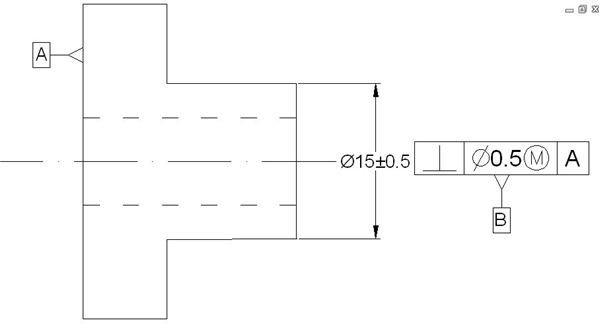
See the following image for an example of how typically the datum features A and B are used in the drawings:
In the above example, the left hand vertical surface and the cylindrical feature of the right are taken as datum features.
Datum
Datums are theoretically perfect but imaginary planes, axises, and points used for creating reference frame in a drawing. This reference frame is used for dimensioning for the drawing and model creation. Datums are established from the datum features. If you have a point datum, then only one datum is sufficient to constrain the model. In the case of planes, you need three mutually perpendicular ones. If you have axis and plane, then one axis and one plane will suffice for the need.
The above drawing has two datum features and hence two datum: an imaginary plane at the left hand surface of the part and the axis of the hole.
Datum Target
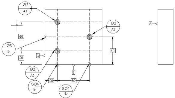
Datum targets also are generated from the datum features. But, for specifying the datum targets we use some portions of the datum features. The sole purpose of the datum target is for locating or constraining the part to a fixture. As per the 3-2-1 principle , we typically define three primary datum targets, two secondary datum targets, and one tertiary datum targets. In the below example, the primary datum targets “A1”, “A2” and “A3” are circular surfaces of diameter 2, the secondary datum targets “B1” and “B2” are the surfaces of diameter 4 and the tertiary datum targets “C1” is of diameter 5.
Conclusion
The datum feature, datum, and datum target are the important geometric dimensioning and Tolerancing (GD&T) concept for creating and manufacturing a model. The datum is an imaginary but theoretically perfect surface, line, or points. A datum feature, on the other hand, is the physical representation of datum. Datum targets are specified regions of the datum feature used for locating the part in a fixture.
Related Readings
GD&T Tutorial on Bonus Tolerance :This geometric dimensioning and Tolerancing tutorial will discuss about the concept of bonus tolerance and the example of the GD&T.
GD&T Tutorial – Learn How to Identify the Feature of Size Dimension :This GD&T tutorial will talk about the concept of feature, feature of size, non-feature of size and also about the application and identification of the geometric dimensioning and Tolerancing concept in engineering drawing.