This article will discuss drive shaft design concepts and shaft design formulas for shafts subjected to combined bending and torsion loading.
In my previous article I have discussed how to design a drive shaft only for bending . But, for many practical shaft design problems you have to consider bending as well as torsional load when designing the shaft. Such drive shaft design problem can be solved in two ways:
- By calculating the equivalent bending moment and toque of bending and torsion.
- By using the principle stress concept.
In this article we will limit our discussion to the equivalent bending moment and torque method.
Equations to Be Used
- Equivalent bending moment equation:
Meqv. = 0.5 [M + SQRT (M^2 + T^2)]……………..eqn.1.1
- Equivalent torque equation:
Teqv. = SQRT (M^2 + T^2)………………………..eqn.1.2
- Equation of bending stress:
Tb = (32*M/(pi*d^3)………………………………eqn.1.3
- Equation for torsional shear stress:
St = (16*T)/(pi*d^3)………………………….eqn.1.4
Where,
Meqv. – Equivalent bending moment
M – Bending moment
T – Torque
Tb – Bending stress
St – Shear stress
d – Diameter of the circular shaft
Shaft Design Problem for Combined Bending and Torsion
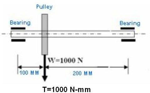
Refer the picture above, apart from the self weight (1000N) of the pulley a torque (1000 N-mm) due to belt tension is also applied on the shaft. Assuming the maximum allowable stress in tension for the shaft material as 40 MPa, The following steps need to be performed for obtaining the minimum diameter of the shaft as per maximum principle stress theory:
Maximum bending moment applied on the shaft = 1000 * 100 = 100000 N-mm
Applied torque is given as 1000 N-mm.
Equivalent bending moment (from eqn.1.1):
Meqv.= 1207 Mpa
- Equivalent torque ( from eqn1.2):
Teqv.= 1414 N-mm
- Maximum principle stress (from eqn 1.3):
Sigma1 = Tb= (12301/d^3)
- Now for getting minimum shaft diameter as per maximum principle stress theory, we have to equate Sigma1 with allowable stress, hence:
40 = (12301/d^3)
Or, d = 6.7 mm
Conclusion
Most of the time you will come across a shaft design problem with the combination of bending and torsional loading. Accurate use of the four shaft design formulae will lead to the solution for most cases. You can get help from the FEA tools as well.
Related Reading
Tutorials on basic mechanical design calculations : Nowadays lots of software tools are available in market to take care about the lengthy calculations. These tools definitely help to drastically reduce the design and design validation time but being a good design engineer one should always be in position to cross check somehow by manual calculations.