Correct welding size calculation and specifying it in welding drawing is the important first step toward achieving defect free welding. This welding design tutorial will explain how to calculate welding size based on simple tensile loading.
Exact welding size calculations may vary based upon the geometry of the welded plates. The example we discuss here will give you an overview, and same methodology can be applied effectively for design calculations of all types of lap weld joints under pure tensile loading.
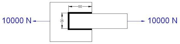
Please refer to the welding joint picture below. (Click to enlarge.)
As a welding design engineer, your task is to find the weld size or leg length based on the given loads and welding rod filler material strength.
Input Data
Applied force F = 10000 N
Total length of the weld L = 50+50+25 MM= 125 mm
Design stress of the filler material Pw = 220 N/mm2
Steps for Calculating Welding Size
- Assume throat thickness for the weld as t.
- The total area (A), which is resisting the force F can be calculated as:
A = L*t
=125* t mm2
- Developed shear stress (T) in the weld can be calculated as:
T = F/A
= 10000/(125*t) N/mm2
- In order to sustain the welding design T should be at least equal to Pw.
T =Pw
Or, 10000 / (125*t) = 220
Or, t = 0.36 mm
- Leg length (s) of the weld can be calculated from the following equation:
s = 1.414 * t
= 1.414 * 0.36 mm
= 0.509 mm (0.6 mm approx.)
Conclusion
The above example explains the steps for calculating welding joint for lap joint and for pure tensile loading conditions. For complex bending and torsion loading line method is used for calculating welding sizes. FEA tools can play important role for calculating correct weld size for extremely complicated joints.
Related Reading
- AWS Welding Symbols for Five Most Useful Weld Types : AWS welding symbols are widely accepted for welding drawing. AWS symbols and ANSI symbols are same. All the AWS weld symbols are derived from the standard called AWS A2.4. We will discuss about five important weld joints types and their AWS welding symbols in this article.