Selecting the correctly sizez steel I beam is very important for your structural design. Gain more understanding of the selection procedure for a steel I beam for given load specifications.
A steel I beam typically has the following important features or dimensions. (Please refer to the picture below):
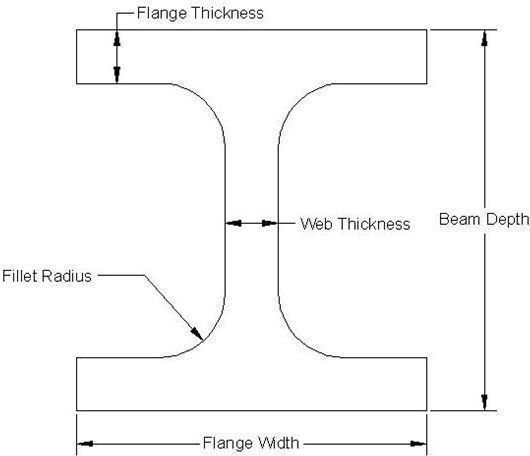
I-Beam Terminology
- Flange thickness: Top and bottom horizontal plate-like sections of an I-beam are called flangen. The thickness of the flanges is called the flange thickness.
- Flange width: The width of the flanges is called flange width.
- Beam depth: The height between the top and bottom surface of the steel I beam is called beam depth.
- Web thickness: The vertical section of steel I beam is called web, and the thickness of the web is called web thickness.
- Fillet radius: The curved portion, where the transition between the web and flange happens is called a fillet. The radius of the fillet is called the fillet radius.
Steps for Selecting a Correctly Sized I Beam
The overall procedure of selecting the correct size of the I beam is based upon basic mechanical design calculations as follows:
The first input you need is the steel I beam load specifications or loading details on the steel I beam.
Draw bending moment diagram for the given loads and you will find the value of maximum bending moments (say M) that the steel I beam is expected to experience.
Choose an approximate size of steel I beam from a standard I beam table .
Find out the area moment of inertia (say I) of the selected steel I beam.
Get the beam depth (say d) of the selected steel I beam.
Now use the following formulae for calculating stress developed (f) in the beam:
f/(d/2)=M/ I
f is the bending stress
M - the moment at the neutral axis
y - the perpendicular distance to the neutral axis
I - the area moment of inertia about the neutral axis x
- Compare the calculated value of the bending stress with the yield stress of the steel in order to check the safety factor of your design.
Conclusion
Correctly sized I beam selection is the first step toward correct structural design. The procedure explained above is based upon static I beam load specifications. In the cases where dynamic loads are involved, you need to use FEA tools like ANSYS , Pro Mechanica , etc.
See also
Five Casting Design Tips – Useful for Casting Product Designer : Casting component design requires special attention for the successful manufacturing of a component. This article will talk about some important casting components design considerations.
How to design a valve spring : The valve springs are a critical component for any engine’s performance. This article will talk about how to design a valve spring.