The Manning Equation Relates Stormwater Flow Velocity in a Storm Sewer to Pipe Roughness and Hydraulic Radius
Introduction
Hydraulic design of storm sewers requires calculations involving flow velocity of the stormwater, storm sewer diameter and slope, pipe roughness coefficient, and storm water runoff flow rate. The Manning Equation is typically used for such calculations, because the storm water flows under gravity and thus is open channel flow. The hydraulic radius, which appears in the Manning equation, becomes D/4 for a circular storm sewer flowing full.
The Manning Equation for a Circular Pipe Flowing Full
The Manning equation for uniform open channel flow in general is: V = (1.49/n)(Rh2/3)(S1/2), where
V = flow velocity, ft/sec
S = pipe slope, ft/ft or dimensionless
n = Manning roughness coefficient (an empirical, dimensionless constant)
Rh = hydraulic radius = cross-sect. area/wetted perimeter
For a circular pipe flowing full, the hydraulic radius is: Rh = (πD2/4)/(πD) = D/4
Thus the Manning equation for a circular pipe flowing full becomes: V = (1.49/n)[(D/4)2/3](S1/2)
This is a very useful equation relating the storm water flow velocity, V; the storm sewer diameter, D; the storm sewer slope, S; and the pipe roughness coefficient, n.
The relationship among flow rate, flow velocity, and cross-sectional area (Q = AV) can be used to introduce stormwater runoff flow rate into the Manning equation. For a circular storm sewer flowing full:
Q = (πD2/4)V = (1.49/n)(πD2/4)[(D/4)2/3](S1/2).
Storm Sewer Hydraulic Calculations
For storm sewer hydraulic design, the design storm water runoff flow rate, Qdes, is usually calculated with the rational method, based on a design rainfall intensity.

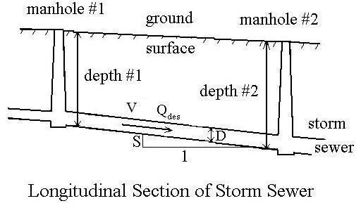
Also, a minimum flow velocity, Vmin, is typically specified for the case where the storm sewer is flowing full. With known values for design stormwater runoff flow rate, Qdes, minimum full pipe flow velocity, Vmin, and the pipe roughness coefficient, n, the Manning equation and the equation, Q = VA, can be used to calculate the design values for storm sewer pipe diameter, D, and slope, S, between adjacent manholes. The parameters for this type of calculation are shown in the diagram at the left.
Example Calculation with Manning Equation
Problem Statement: The design flow rate for a section of storm sewer between two manholes is: Qdes = 8.3 cfs. The required minimum stormwater flow velocity is: Vmin = 3 ft/sec. The pipe will be concrete with pipe roughness coefficient: n = 0.012. Find a combination of a standard pipe diameter and pipe slope to use for this section of storm sewer to meet the two criteria: Qfull > Qdes and Vfull > Vmin.
Solution: As the first step, calculate the pipe diameter needed to give a full pipe flow velocity of Vfull = 3 ft/sec when the storm sewer is carrying the design flow rate of stormwater, 8.3 cfs. The equation, Q = VA allows us to do this. For this situation, the equation becomes: Qfull = Vfull(πD2/4). Substituting specified values, the equation becomes: 8.3 = 3(πD2/4). Solving for D: D = 1.877 ft = 22.5 in. The standard pipe sizes for most types of pipe used for storm sewers are those listed in the next section. The next standard size larger than 22.5 inches is 24 “, so that will be selected for the diameter.
Now use the Manning equation to calculate the slope for D = 24 in. = 2 ft, and V = 3 ft/sec. The Manning equation is: V = (1.49/n)[(D/4)2/3](S1/2). With values for V, D, and n substituted, it becomes: 3 = (1.49/0.012)[(2/4)2/3](S1/2). solving this equation for S gives: S = 0.0015.
The solution is: D = 24”, S = 0.0015. These values of D and S will give Qfull > 8.3 cfs, because Qfull = 8.3 cfs for Vfull = 3 ft/sec and D = 22.5". With D = 24 " and V = 3ft/sec, Qfull must be greater than 8.3 cfs. The last equation in the second section of this article can be used to check this.
For an article with a downloadable Excel spreadsheet template for making storm sewer design calculations, see “Stormwater Sewer Design using Excel Formulas in a Spreadsheet Template.”
Standard Pipe Diameters
Standard pipe diameters (all in inches) for most types of pipe used as storm sewers are:
4, 6, 12, 15, 18, 21, 24, 27, 30, 33, 36, 39, 42, 48, 54, 60, continuing with 6" increments up to 180 inches.
References and Image Credit
References for further information:
1. Bengtson, Harlan H., Hydraulic Design of Storm Sewers, Including the Use of Excel, an online, continuing education course for PDH credit.
2. McCuen, Richard H., Hydrologic Analysis and Design, 2nd Ed, Upper Saddle River, NJ, Prentice Hall, 1998.
3. Steele, E.W. and McGhee, T.J., Water Supply and Sewerage, New York, NY, McGraw-Hill Book Co, 1979.
Image Credits:
1. Storm Sewers and Sanitary Sewers - City of Shaker Heights, Ohio
2. Longitudinal Section of Storm Sewer - from Reference #1
This post is part of the series: Storm Sewer Hydraulic Design
Articles in this series on storm sewer hydraulic design cover finding the design stormwater runoff rate with the rational method; calculating the diameter and slope of each section of storm sewer using the Manning equation; the depth at each manhole; and an Excel template for making the calculatons.
