Heat Exchanger Theory and the Heat Exchanger Design Equation
Introduction
The heat exchanger design equation can be used to calculate the required heat transfer surface area for a variety of specified fluids, inlet and outlet temperatures and types and configurations of heat exchangers, including counterflow or parallel flow. A value is needed for the overall heat transfer coefficient for the given heat exchanger, fluids, and temperatures. Heat exchanger calculations could be made for the required heat transfer area, or the rate of heat transfer for a heat exchanger of given area.
The Heat Exchanger Design Equation
Heat exchanger theory leads to the basic heat exchanger design equation: Q = U A ΔTlm, where
Q is the rate of heat transfer between the two fluids in the heat exchanger in But/hr,
U is the overall heat transfer coefficient in Btu/hr-ft2-oF,
A is the heat transfer surface area in ft2,
and ΔTlm is the log mean temperature difference in oF, calculated from the inlet and outlet temperatures of both fluids.
For design of heat exchangers, the basic heat exchanger design equation can be used to calculate the required heat exchanger area for known or estimated values of the other three parameters, Q, U, and ΔTlm. Each of those parameters will now be discussed briefly.
Log Mean Temperature Difference
The driving force for any heat transfer process is a temperature difference. For heat exchangers, there are two fluids involved, with the temperatures of both changing as they pass through the heat exchanger, so some type
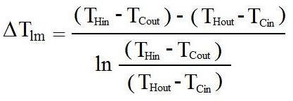
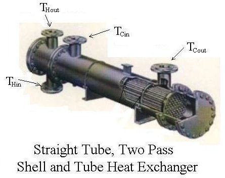
of average temperature difference is needed. Many heat transfer textbooks have a derivation showing that the log mean temperature difference is the right average temperature to use for heat exchanger calculations. That log mean temperature is defined in terms of the temperature differences as shown in the equation at the right. THin and THout are the inlet and outlet temperatures of the hot fluid and TCin and TCout are the inlet and outlet temperatures of the cold fluid. Those four temperatures are shown in the diagram at the left for a straight tube, two pass shell and tube heat exchanger with the cold fluid as the shell side fluid and the hot fluid as the tube side fluid.
Heat Transfer Rate, Q
Heat exchanger calculations with the heat exchanger design equation require a value for the heat transfer rate, Q, which can be calculated from the known flow rate of one of the fluids, its heat capacity, and the required temperature change. Following is the equation to be used:
Q = mH CpH (THin - THout) = mC CpC (TCout - TCin), where
mH = mass flow rate of hot fluid, slugs/hr,
CpH = heat capacity of the hot fluid, Btu/slug-oF
mC = mass flow rate of cold fluid, slugs/hr,
CpC = heat capacity of the cold fluid, Btu/slug-oF,
and the temperatures are as defined in the previous section.
The required heat transfer rate can be determined from known flow rate, heat capacity and temperature change for either the hot fluid or the cold fluid. Then either the flow rate of the other fluid for a specified temperature change, or the outlet temperature for known flow rate and inlet temperature can be calculated.
Overall Heat Transfer Coefficient, U
The overall heat transfer coefficient, U, depends on the conductivity through the heat transfer wall separating the two fluids, and the
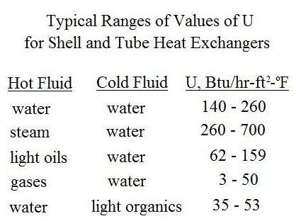
convection coefficients on both sides of the heat transfer wall. For a shell and tube heat exchanger, for example, there would be an inside convective coefficient for the tube side fluid and an outside convective coefficient for the shell side fluid. The heat transfer coefficient for a given heat exchanger is often determined empirically by measuring all of the other parameters in the basic heat exchanger equation and calculating U. Typical ranges of U values for various heat exchanger/fluid combinations are available in textbooks, handbooks and on websites. A sampling is given in the table at the right for shell and tube heat exchangers:
Summary
Preliminary heat exchanger design to estimate the required heat exchanger surface area can be done using the basic heat exchanger equation, Q = U A ΔTlm, if values are known or can be estimated for Q, U and ΔTlm. Heat exchanger theory tells us that ΔTlm is the right average temperature difference to use.
For example preliminary heat exchanger design calculations, see the article, “Preliminary Heat Exchanger Design Example.”
For Excel spreadsheet templates that can be downloaded to make preliminary heat exchanger design calculations, see the article: “Excel Spreadsheet Templates for Preliminary Heat Exchanger Design.”
References and Image Credit
References for Further Information:
1. Bengtson, H., Fundamentals of Heat Exchangers, an online, continuing education course for PDH credit
2. Kakac, S. and Liu, H., Heat Exchangers: Selection, Rating and Thermal Design, CRC Press, 2002.
3. Kuppan, T., Heat Exchanger Design Handbook, CRC Press, 2000.
Image Credit:
Straight tube, two pass, shell and tube heat exchanger: https://www.e-steamboilers.com/en/shell_tube_heat_ex.asp
This post is part of the series: Heat Exchanger Design
Heat exchanger design includes estimation of the heat transfer area needed for known or estimated heat transfer rate, overall heat transfer coefficient and log mean temperature difference. The tube or pipe diameters and length also need to be determined, as well as the pressure drop.