Build a Zener Diode Regulation Circuit
Introduction
Zener diodes are not new to us and we already know quite a lot about them. Basically, they are used to fix or clamp the voltage to a particular level depending upon their voltage rating. Typically, these voltages are used as reference levels by the preceding stages and invariably the whole circuit becomes critically depended on these particular references. But how do they exactly do this? The functioning is very simple and can be explained as follows:
If suppose for example, a supply voltage of 12 volts is applied across a 6 volt rated zener diode, as per the characteristic, a zener diode will short circuit or ground any voltage that’s above its rated value. It simply means that the voltage cannot rise above 6 and will be fixed at that level. In this way a zener diode is able to create and sustain a fixed voltage level across its terminals.
But, short circuiting a voltage would mean draining heavy currents which may in turn blow the zener diode or the associated safety fuse. Therefore, to avoid this, a resistor is always added in series with a zener diode. The resistor helps in restricting the current through the diode and thus safeguarding it from certain damage otherwise.
However, since the resistor will restrict a lot of current, also implies that this type of voltage regulation cannot be used in places where the current requirement is high, and therefore zener stabilizations are specifically used only as voltage references with transistors and ICs, where low currents may not be a matter of concern.
The following section will explain how a zener diode may be configured into simple zener diode voltage regulation circuits and used as voltage references for various applications.
Building Zener Diode Voltage Regulation Circuits
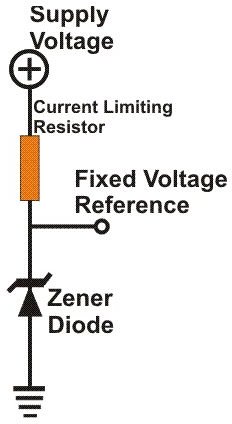
A most common and standard configuration using a zener diode is shown in the adjoining figure. As explained above, the resistor helps in controlling the current through the zener and also becomes the maximum available output source current. Since current value is not very critical, the resistor value is also not critical; at 12 volts any value between 2K2 and 10 K will do the job nicely.
However, variation in the input voltages may cause an increase in the current through the zener and can affect the stabilized voltage value. As the current through the zener increases, the reference value set by it will decrease proportionately. This may cause serious malfunction in the overall circuitry. Fortunately, this problem may be accurately dealt with using just a couple of transistors and few other passive components. The configuration has been elaborately explained HERE.
While designing electronic circuits, sometimes it becomes difficult to ascertain a particular reference level for a circuit. Since every zener diode has a particular fixed value, the task becomes quite tedious as then we have to select the required value by connecting and checking the different available zener values many times.
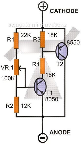
In such situations a continuously variable zener diode may become pretty handy and solve the problem very efficiently. One such simple circuit is shown alongside. Varying the pot of the circuit effectively changes the “zener” or the regulation voltage of the circuit across its terminals. Thus, by simply connecting the two terminals of the circuit to the points where a normal zener diode would be connected and by varying its pot, the required value for a circuit may be easily fixed.
According to the particular setting of VR1, a proportionate amount of current flows through R3, R4 and T1, this in turn switches T2 proportionately. T2 stops T1 from further conducting and clamps a particular equivalent voltage level across its terminals. As VR1 is varied this clamping voltage will vary proportionately enabling to acquire different “zener” values comfortably. But, remember to connect a series resistor with the circuit just as you would do with a normal zener diode.
The regulation voltage of this variable “zener diode” can be varied right from 3 to 25 volts, smoothly and fractionally.