Ghost Detection Equipment - Learn to Build Your Own RF Detector
Introduction
Being an electronic enthusiast myself, most of the time I am busy inventing and developing new electronic circuits. Click here to read about making your own DC to DC mobile charger. While working on a project of a mobile phone RF signal detector, I developed this interesting circuit which can detect the minutest of RF or electromagnetic disturbances in the ether. Whether its a flickering of a tube light, a call on your cell phone or a distant thunder storm, the circuit will never miss a thing. People who are intrigued by the possible existence of supernatural forces may also try this circuit as a ghost detection equipment. Though I wont guarantee any positive results for this, It’s always good to keep your fingers crossed.
The circuit is actually very easy to construct and can be built even by an electronic novice.
Parts Required
To begin with first procure the following components from your local spare parts dealer:
- IC 324 - 1 no.
- capacitor 10 nF - 1 nos.( ceramic disc ),
- resistor 10 M, 100 k - 2 nos. each, 470 Ohms - 1no.( 1/4 watt CFR 5% ),
- LED red - 1 no.( red ),
- General purpose board - 2/4 “.
About IC 324
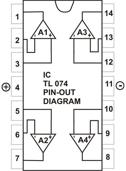
It is 14 pin DIL quad op amp IC. Its pin details are as follows:
- Pin 2 is inverting input, pin 3 is non inverting input and pin 1 is the out put of the 1st op amp.
- Pin 5 and pin 6 are the inverting and non inverting inputs, and pin 7 is the out put of the 2nd op amps.
- Similarly pin 9 / 10 and pin 13 / 14 are the inverting and non inverting inputs of the 3rd and the 4rth op amp, and pin 8 and 14 are their outputs respectively.
Assembly
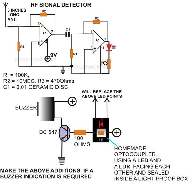
For this you will need a soldering iron, solder wire and a lead cutter, start the assembly as follows:
- Fit and solder the IC lengthwise somewhere in the centre of the board,
- Connect the 10 M resistors to non inverting and output pins of each op amp, also connect 100 k resistors to the inverting pins of each op amps and ground all the free ends of the 100 k resistor,
- Solder the anode of the LED to the output of the 4rth op amp and ground its cathode with a series resistor of 470 Ohms. Also connect a six inches wire to the in put (pin 2) of the 1st op amp as an antenna,
- By soldering the 10 nF capacitors, couple the out put of each op amp to the input of the next, starting from the first op amp and ending at the 4rth,
- Finally connect positive supply to pin 4 and negative to pin 11 of the IC from a 9 volt battery only.
Testing
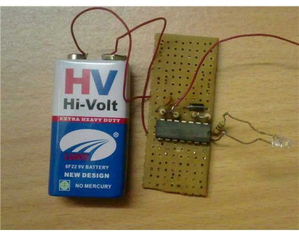
Bring a gas lighter very close to the antenna and start clicking, if all the wirings are done correctly the LED should start flickering in accordance with the clicking right-away.
Enclose the whole circuit in a suitable sturdy plastic box with the antenna protruding out of the box.
Bravo, you are now free to go for a ‘ghost hunting’ with this ‘ghost detector’, but wait please don’t panic if the LED starts flickering intermittently, It might just be your friend next door making a call on his cell phone!
Interesting Modification
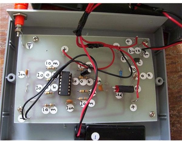
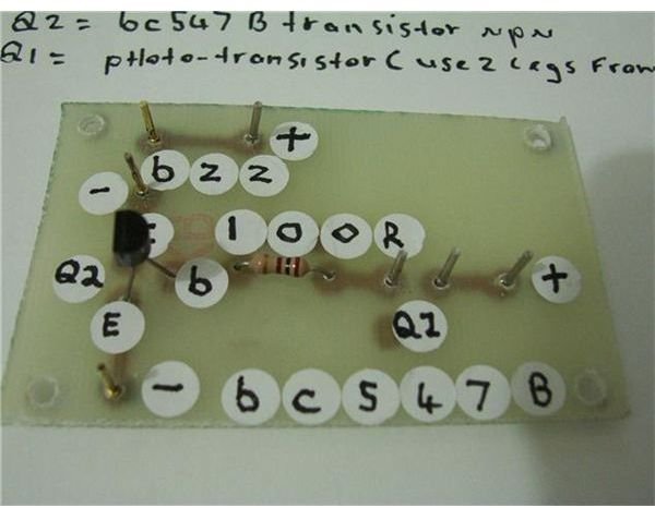
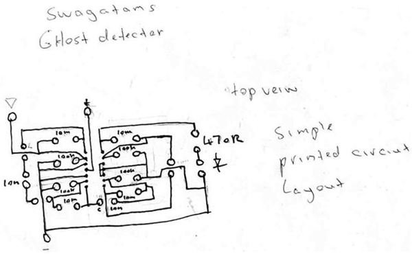
A dedicated reader and electronic enthusiast Steven Chiverton has done an interesting modification in the above circuit. He found out that by introducing a 0.1 uF capacitor across the right hand side 100 K resistor increased the sensitivity of the circuit to a great extent. He also developed a simple way of making an opto-coupler so that the circuit may be equipped with a strong audio tone.
The images shown alongside indicates his intense effort.
