Robot builders who are interested in building a mobile robot usually experiment with different types of DC brush motors. Fortunately, they are very easy to test by building simple DC motor circuits. All that is needed is a DC brush motor, battery, and red and black alligator leads.
The Simple DC Motor Circuit
Selecting a Motor for the Simple DC Motor Circuit
This article will only be dealing with simpler permanent-magnet DC brush motors. More complex motors such as the DC b
All small-sized double-wire permanent-magnet DC brush motors are essentially the same. Some have wire leads while others have metal connector terminals. Further, some motors have shafts with pulleys or gears attached while others don’t. Nonetheless, all are sufficient for building a simple DC motor circuit.
Selecting a Battery for the Simple DC Motor Circuit
Most sma
Building the Simple DC Motor Circuit
As seen by the figure to the right, the simple DC motor circuit is, as stated by its name, quite simple. In the figure, B1 stands fo
The Specialized DC Motor Circuit
Although the simple DC motor circuit is useful for testing motors, it is not practical when you’re trying to control a motor. Therefore, a unique circuit, called the specialized circuit or motor driver, is used to electronically control the function of DC motors. A common circuit that is used to drive DC motors is the H-bridge. An H-bridge consists of a combination of transistors that allow complete control over a DC motor. The reason that the H-bridge is so commonly used is due to its versatility. It can be used to design a basic circuit, or a more complex circuit that protects the DC motor from damage. Below I have included an example of a simpler H-bridge circuit design.
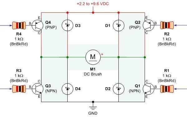
The different parts of the circuit are as follows:
- Q1 and Q3 are NPN bipolar junction transistors which connect the DC motor to the negative terminal of the battery.
- Q2 and Q4 are PNP bipolar junction transistors which connect the DC motor to the positive terminal of the battery.
- R1-R4 are resistors that control the amount of current that is delivered to the DC motor.
- D1-D4 are diodes that safely allow current to travel back to the battery when the DC motor is made to stop.
- M1 is the DC motor.
All of these various parts work together to allow remote controls to cause a DC motor to spin forwards, spin backwards, slow down, and stop.
Images Courtesy
- DC brush motor: https://catalog.miniscience.com/Catalog/Motors/images/RE140RA_DC_Motor_With_Wire_L1.jpg
- AA batteries with holder: https://img221.imageshack.us/img221/7637/aabatteries.jpg
- Simple DC motor circuit: https://img441.imageshack.us/img441/9551/dcmotorcircuit.jpg
- H-bridge: https://www.robotroom.com/BipolarHBridge/BipolarHBridgeSchematic.gif
About the Author
Terry Ligard is a fourth year mechanical engineering student at the University of Alberta. Terry has several months of experience building electromechanical transporters.


