Quick Take
This article will discuss how to draw a stool with CAD; we will see the procedure of creating the stool using AutoCAD as well as ProE.
On this page
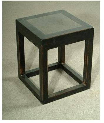
You can use either a 2D CAD system or a 3D CAD system for creating the stool with CAD. We will use AutoCAD as 2D and ProE as 3D CAD system. We will create a stool like below:
Creating Stool Using AutoCAD
- You can create the stool drawing either by using the icons or by using the autocad commands . We will discuss the commands here, as it is the faster method.
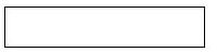
Type the rectangle command at the command section of the AutoCAD and draw a 500mm X 100mm rectangle like below:
- You can create the stool drawing either by using the icons or by using the commands. We will discuss the commands here, as it is faster method.
- Type the rectangle command at the command section of the AutoCAD and draw a 500mm X 100mm rectangle like below:
- Now type the alphabet x or the word explode at the command section to convert the rectangle to the group of line entities.
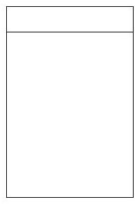
- Key the command offset or the letter o to offset the top horizontal line downward by a distance of 700 mm.
- Extend the two vertical lines of the rectangle up to the just created offset line by using the extend command**.** You will get the geometry like below:
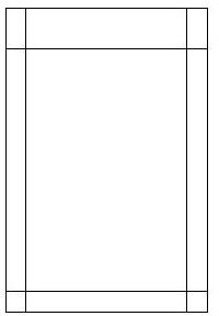
- Offset the two parallel vertical lines by 50mm to inside direction.
- Offset the bottommost horizontal line by 50mm in upward direction. You will get a drawing like below:
- Trim the required portions by using the trim command and you side view of the stool is ready like below:
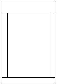
- Save the AutoCAD file.
Creating Stool Using ProE
- Run ProE by hitting the ProE shortcut.
- Go to file>new and create a new ProE part file and name it as top_plank.
- Go to insert>extrude create a square extrude part of size 500mm X 500mm X 10mm.
- Save it.
- Create another part file named side_plank.
- Create a extrude part of size 400mm X 90mm X 10mm.
- Save it.
- Similarly, create a part named leg of size: 690mm X 50mm X 50mm.
- Create another part file named bottom_tie. The size of the bottom_tie should be 400mm X 50mm X 50mm.
- Now you have to assemble the different parts you have just created.
- Create a ProE assembly file named stool.
- Go to insert>component>assemble and add the top_plank at the default position.
- Next, add the leg, use the align constraints to place it at a corner of the top_plank.
- Similarly, add the three other legs as well.
- Add the bottom_tie and place them in between the pairs or legs.
- Add the side_plank just under the top_plank and in between the pairs of legs.
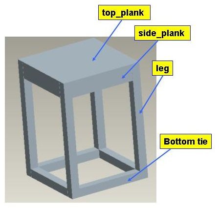
- Save the assembly and the 3D CAD model of the stool is ready like below:
- · Run ProE by hitting the ProE shortcut.
- · Go to file>new and create a new ProE part file and name it as top_plank.
- · Go to insert>extrude create a square extrude part of size 500mm X 500mm X 10mm.
- · Save it.
- · Create another part file named side_plank.
- · Create a extrude part of size 400mm X 90mm X 10mm.
- · Save it.
- · Similarly, create a part named leg of size: 690mm X 50mm X 50mm.
- · Create another part file named bottom_tie. The size of the bottom_tie should be 400mm X 50mm X 50mm.
- · Now you have to assemble the different parts you have just created.
- · Create a ProE assembly file named stool.
- · Go to insert>component>assemble and add the top_plank at the default position.
- · Next, add the leg, use the align constraints to place it at a corner of the top_plank.
- · Similarly, add the three other legs as well.
- · Add the bottom_tie and place them in between the pairs or legs.
- · Add the side_plank just under the top_plank and in between the pairs of legs.
- Save the assembly and the 3D CAD model of the stool is ready like below:
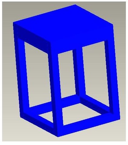
- You have to render it for changing it color and/or texture, for that go to view>color and appearance and the appearance editor will open up.
- Choose a color suitable to you and click apply. I have chosen blue color and the stool finally looks like below:
Conclusion
The article has explained how to draw stool with CAD by using the AutoCAD and ProE . You can use any other 2D and 3D CAD packages for creating and rendering stool, the overall method will be similar.