This Unigraphics (UGS or UG) tutorial on datum point will discuss about five important types of UGS datum point, their usage and the method of creation.
Your working efficiency with Unigraphics is largely dependent upon your understanding of UGS datum features . Datum points are one such datum feature. There are thirteen types (or methods) of datum points in Unigraphics. We will discuss about five most useful types of UGS datum points here in this UG tutorial:
1. Inferred Point: This is the most versatile method of datum point creation in UGS. You can create a datum point literally at all possible places (end point, control point, existing point, on surface and at cursor location) of your UGS model.
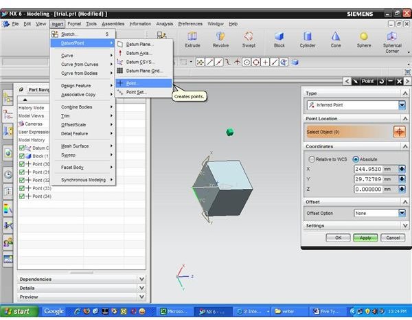
Procedure: Go to insert→Datum Point→Point and you will get the “point creation dialogue box” open as below:
Select Inferred point as point type and select the location. Click “OK,” and that’s it.
2. Cursor Location: The datum point will be created at the cursor location and in the working plane (XY). So, if you want to create point in any other plane than the working plane, then you need to change the working plane accordingly.
Procedure: Go to insert→Datum Point→Point and you will get “point creation dialogue box**.”** Now select “Cursor Location” as the type in the dialog box. And select desired location of the datum point by mouse click.
3. Existing Point: By this method you can create point coinciding to any existing point.
Procedure: Go to insert→Datum Point→Point and you will get “point creation dialogue box**.”** Now select “Existing Point” as the type in the dialog box. And select any existing point by mouse click.
4.End Point: You can create a point at the end points of a geometric entity. For example, you can create a datum point at the end of a line by this method.
Procedure: Go to insert→Datum Point→Point and you will get “point creation dialogue box**.”** Now select “End point” as the type in the dialog box. Select the end point where you want the datum point to be.
5. Control Point: This method is useful for creation of point at the position of control points of the curves.
Procedure: Go to insert→Datum Point→Point and you will get “point creation dialogue box.” Now select “Control point” as the type in the dialog box. Select the control point from the model.
Conclusion
In many cases, the datum points act as a building block of your UGS sketch and 3D model. Selection of the correct UGS datum point creation method is important for getting the Unigraphics datum point in the desired location. Methods explained in this Unigraphics tutorial will be handy for most of the practical situation of your UGS 3D modeling .
Related Reading
- What is Suppressed Geometry in Unigraphics : Using of suppressed geometry is very much helpful if not inevitable for handling large Unigraphics model. In this Unigraphics tutorial, we will discuss about creation and usages of UG suppress geometry.
- ProE Wildfire vs. UG NX 6 : ProE as well as UG both are high end 3D CAD package. While comparing ProE vs. UG in this article we will discuss which one is strong in which area.