Protrusion is one of the most used features, not only in Solid Edge, but in all 3D CAD packages. Here we’ll look at how Solid Edges “SmartStep” ribbon bar makes creating a protrusion easy, logical, and quick.
Around 70% of the time only protrusion and cut are used in CAD drawing. If you look at a 3D CAD model of any system of a car, you will see that most of the drawing starts with protrusion. Probably you can create a protrusion even blindly in any application, but the challenge is to create it in some desired position. We will discuss here how to create a protrusion in Solid Edge.
How to create protrusion?
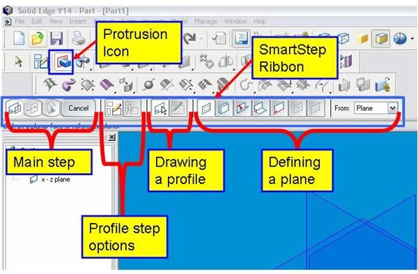
Solid Edge is a completely icon-based 3D CAD package. You need to click the protrusion icon first. See the snap below. (Hover mouse to read the label or click to enlarge).
The SmartStep Ribbon then appears. The ribbon is very task-oriented and has four sections. The icons at the left-most section up to the “Cancel” button represent the main steps of any Solid Edge feature operation. For creating a protrusion, we are having following main steps:
1. Profile step: Here you will be drawing or selecting a base sketch for creating the protrusion. In the snap below, this step is in active mode. Hence you have the following sub steps:
I. Profile step options: You can select an option of either drawing a sketch or using a previously created sketch here.
II. Drawing a profile: Here you will be selecting an option for either drawing a profile on plane or editing the base sketch of an existing drawing.
2. Side step: This step decides on which side of the sketching plane/surface the protrusion will be created. While creating a protrusion, side is selected by mouse click.
3. Extent Step: Depth/height options of a protrusion are controlled by this step. We have following different options for depth/height:
I. Through all: Extend the protrusion through all the faces of the body.
II. Through next: The sketch is extruded up to the next intersection surface at the selected direction.
III. From/To extent: The sketch is extruded from a selected face up to a selected face.
IV. Finite extent: Here you have to specify depth of the protrusion.
For every steps/sub-step there will be instructions displayed just below the SmartStep ribbon.
Editing a protrusion
If you need to change some of the parameters of a previously created protrusion, you should right click on the protrusion and click on “Edit definition” and you will get the ribbon bar again with the main steps. Click on the main step where you want the change, and you will get the respective sub steps. For example if you want to modify the sketch, go for “Profile step” and then “Draw profile step” to go the sketch for editing. Once you finished editing click “Finish.”
Protrusion is the basic and most used feature of Solid Edge as well as most of the other 3D CAD packages. The SmartStep ribbon and instructions guide the user through the protrusion creation process in Solid Edge.