SolidWorks is a popular CAD program. The latest version, SW2008 released in September , has several new features as well as new look. This article will explain the new and old sketch entities – line, rectangle and circle creation.
Introduction
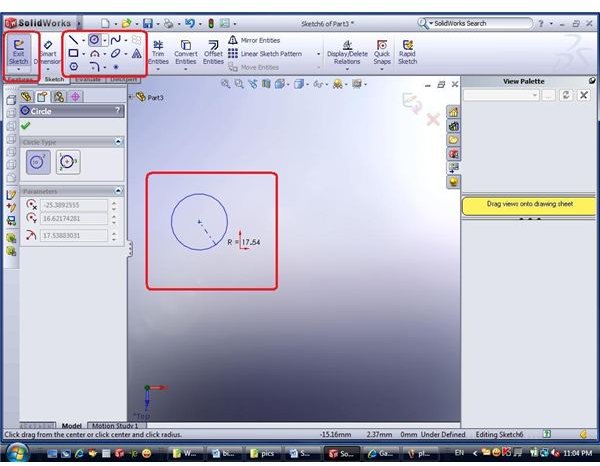
We have mentioned that modeling in SolidWorks is all about sketches. Once you have decided to create a sketch (by choosing the sketch plane and clicking on “sketch” feature or any other way), you have ”entered” the sketch. As said, you can know you are “inside” the sketch feature by noticing the “Exit Sketch” button in the upper left of the Upper Menu.
Sketch Entities
Beside that button, you have “Smart dimension” button and further left - the sketch entities. There are several entities that were predefined by the program creators:
- Line
- Rectangle
- Polygon – new in SW2008
- Circle
- Arc (now separate form circle)
- Sketch fillet/chamfer
- Spline
- Ellipse – this is new for SW2008
- Point
- Text
Each entity has several options that appear in the place of feature tree once you have selected you choice – as described below.
Line
Line can be either Regular line or Center line. Center line is used for construction purposes only. This means that the sketch is referencing this line (for instance, when dimensioning the sketch), but it is not actually a part of the sketch and no pane will be created in 3D feature. You can trun the line to construction/regular later as well.
The lines can also be infinite length (new addition in SolidWorks 2008).
Rectangle
There are several ways to define rectangle:
- By 2 corners – just click twice and a rectangle will be created, with its lines parallel to X and Y sketch plane axis.
- By corner and center – click twice, to create a center point (which can later be referenced) and a point on plane, defining one corner. The rest of the corners will be symmetric relative to the center point. This rectangle is also parallel to the sketch plane axis.
- By 3 corners – in this case you must click 3 points on the sketch plane, define 3 corners of the rectangle. This way the rectangle can be “rotated” relative to the plane axis.
- By 3 corners – a combination of Center-corner and 3 corners, defining a rectangle by center point and center line (line of symmetry), and adding a corner to complete the definition. The other 3 corners will result in symmetry relative to the center line and point.
Another option here is the Parallelogram – not really a rectangle, but a also a 4-sided entity. You can define parallelogram by 3 points, constructing 2 lines that form a parallelogram.
Circle
A circle is defined in 2 ways
- By center and radius – click once to set the center point of the circle and second time – to set a point on the circle.
- By 3 points – just click 3 points on the plane that are lying on a circle, defining it completely.
This post is part of the series: CAD modelling with SolidWorks 2008
Are you a CAD user? An engineer? Product designer? What software do you use? Try SolidWorks - and you may never want to switch back… Already a SW user? This series will give you some useful tips about the latest version, SolidWorks 2008.
- CAD software - SolidWorks 2008 Overview
- Learning SolidWorks 2008 – Creating New Part and Menu Structure
- Learning SolidWorks 2008 – Creating a sketch
- Learning SolidWorks 2008 – Sketch Entities – Part I
- Learning SolidWorks 2008 – Sketch Entities – Part II
- Learning SolidWorks 2008 – Sketch Entities – Part III
- What’s new in SolidWorks 2008 – The view menu – part I
- What’s new in SolidWorks 2008 – The view menu – part II
- Learn SolidWorks 2008 – Extrude – part I
- Learn SolidWorks 2008 – Extrude – Part II
- Learn SolidWorks 2008 – Extrude – Part III
- Learn SolidWorks 2008 – Extrude – Part IV